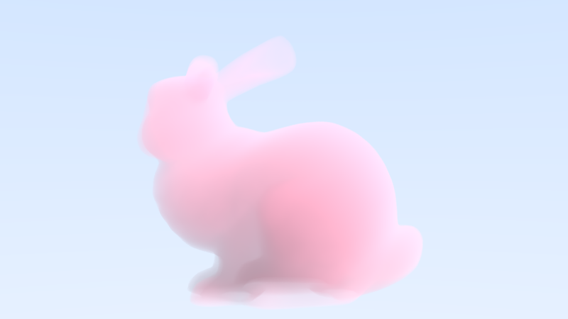
Unlike conventional surface path tracing, volume rendering will account for radiance changes continuously along a ray as it travels through participating media such as fog or smoke. Within the medium, light is attenuated by absorption and out-scattering, with additional radiance may be introduced through in-scattering. These effects are described by the volume rendering equation.
For a ray passing through the volume, the final radiance is approximated by the following discrete single-scattering equation:
The total in scattering effect is evaluated over all ray-marching samples, where
Here, is the final radiance returned along the camera ray .
is the background sky radiance.
is the total transmittance along the camera ray. Therefore,
represents the portion of the sky radiance that remains visible after passing through the volume.
is the total number of ray-marching steps, and is the length of each step.
is the density of the medium at the -th sample position.
is the scattering coefficient. The term approximates the amount of light scattered within the given ray-marching interval.
is the intrinsic color of the volume. It acts as a color filter on the scattered radiance.
is the radiance emitted by the point light.
is the transmittance between the -th sample position and the light source. It is evaluated using a separate shadow ray-marching process.
is the camera-ray transmittance evaluated approximately at the midpoint of the -th interval.
The Henyey–Greenstein phase function describes the angular distribution of scattered light, controlled by the parameter g and the scattering angle between incoming light direction and the camera direction.
For each ray-marching step, according to the Beer–Lambert law, the attenuation factor is
where the extinction coefficient is the sum of the scattering and absorption coefficients:
The camera transmittance is initialized as
After each ray-marching step, it is multiplied by the attenuation factor of the current interval:
Equivalently, the camera transmittance before processing sample can be written in exponential form as
The transmittance at the midpoint of the current interval is approximated as
Substituting the attenuation factor gives
Let’s have a look at the code that implements such math equations:
color volume_camera::ray_color(const Ray& r,const VoxelGrid& grid, constdouble & sigma_s, constdouble &sigma_a, const color & volume_color){ // sky vec3 unit_dir = unit_vector(r.direction); double a = 0.5 * (-unit_dir.z() + 1.0); color sky_color = (1.0 - a) * color(1.0, 1.0, 1.0) + a * color(0.5, 0.7, 1.0); double t0 = 0.0; double t1 = std::numeric_limits<double>::infinity(); if (!grid.hit_box(r, t0, t1)) { return sky_color; //if the ray doesn't hit the voxel grid, then return the sky color } t0=std::max(t0,0.0); if(t1<=t0){ return sky_color; //invalid interval } vec3 light_pos{2.0, 1.5, -1.5}; vec3 light_color{1.0,1.0,1.0}; double light_intensity=20.0; vec3 light_radiance=light_color*light_intensity; doublesigma_t=sigma_s+sigma_a; double g=0.2; //set the step size to roughly half the smallest grid size double step_size=std::min({grid.voxel_size.x(),grid.voxel_size.y(),grid.voxel_size.z()}); step_size*=0.5; int ns=(int)std::ceil((t1-t0)/step_size); ns=std::max(1,ns); step_size=(t1-t0)/ns;
double T=1.0; color in_scatter = vec3{0, 0, 0}; for(int i=0;i<ns;i++){ double t=t0+step_size*(i+random_double(0,1)); //jittered sampling within each integration step (reduces banding) auto pos=r.at(t); double sdf=grid.sample_sdf(pos); //get the sdf at this point double density=sdf_to_density(sdf); //convert it to density if(density<=0){ continue; //avoid useless computation outside the mesh } double Att=std::exp(-sigma_t*density*step_size); //Beer-Lambert transmittance over one step (ray segment extinction) double T_mid =T * std::sqrt(Att); //midpoint approximation of transmittance, T_camera included
vec3 to_light=light_pos-pos; double dis_light=to_light.length(); vec3 to_light_n=unit_vector(to_light); Ray light_ray{pos,to_light_n}; double lt0=0.0; double lt1 = std::numeric_limits<double>::infinity(); grid.hit_box(light_ray,lt0,lt1); double T_light = shadow_T_light_grid(sigma_t,light_ray,grid,lt1); //marching toward the light source to get the shadow transmittance double cos_theta = -dot(to_light_n, unit_dir); //phase function double ph = phase_hg(g, cos_theta); color in_scatter_step = ph * light_radiance * T_light * sigma_s * step_size * density * volume_color; //core rendering equation for in scattering in_scatter += T_mid * in_scatter_step; T=T*Att; //gradually incremented along the way if(T<0.001){ break; //since we apply the forward marching, when T is too small, we can use an early stop } } return sky_color * T + in_scatter; }
Similarly, the shadow ray tracing toward the light source is shown below, where we march along the ray toward the light source.
inlinedoubleshadow_T_light_grid(doublesigma_t, const Ray& r, const VoxelGrid& grid, doubleleave_t){ double T_light=1.0; double step_size=std::min({grid.voxel_size.x(),grid.voxel_size.y(),grid.voxel_size.z()}); step_size*=0.5; int ns=(int)std::ceil((leave_t)/step_size); ns=std::max(1,ns); step_size=(leave_t)/ns; for(int i=0;i<ns;i++){ double t=step_size * (i + random_double(0, 1)); auto pos=r.at(t); double sdf=grid.sample_sdf(pos); double density=sdf_to_density(sdf); double Att=std::exp(-sigma_t*step_size*density); //same Beer-Lambert law for segment extinction T_light=T_light*Att; if(T_light<0.001){ break; } } return T_light; }
VoxelGrid and Signed Distance field
In the previous chapter, we saw that volume rendering requires a continuous density field in space, while a triangle mesh only provides a surface representation. To bridge this gap, we first voxelize the mesh into a regular grid, and then construct a signed distance field (SDF) to capture both inside/outside information and the distance to the closest surface. This SDF is finally converted into a smooth density field.
Then, the shape of the object is no longer stored explicitly. Instead, it is implicitly defined by where the density becomes high in space. The “surface” appears naturally in the transition region of this density field. When we perform ray marching, rays accumulate absorption and scattering along their path. Dense regions block light and contribute to scattering, while empty regions do almost nothing. In this way, the shape is reconstructed indirectly through light transport rather than explicit geometry.
Specifically, the class VoxelGrid divides a bounding box into voxels and with the index function . Then, for each voxel center, the unsigned distance to the closest triangle is computed, and its sign is determined using the even–odd ray casting method.
1
2
3
4
5
6
7
8
auto p = grid.voxel_center(i, j, k);
auto d = point_to_mesh_unsigned_d(p, mesh);
int count = intersection_times(p, mesh, direction);
if (is_inside(count))
{
    d = -d; // inside is negative
}
grid.set_value(i, j, k, d);
Then, linear interpolation is used to evaluate the distance (SDF value) at any point inside the bounding box.